

HELLO,WELCOME TO Dingxin Technology (Shenzhen) Co., LTD WEB
1 Safety precautions
● Be sure to read the instruction manual before turning on the DQ-IP2 transmitter.
● Never open the cover of the machine privately, otherwise the warranty will not be given. In addition, there may be electric shock when touching the inside of the machine, which is very dangerous.
● When the DQ-IP2 transmitter is not used for a long time, please be sure to unplug the power plug. In addition, please do not use damaged electricity. Power socket to avoid fire and electric shock.
● Do not touch the power socket with wet hands, as there is a possibility of electric shock.
● When unplugging the connecting wire, the plug should not be pulled by the wire itself.
● Do not drop flammable materials, metal objects, liquids, etc. into the machine, as these things will damage the device.
● In order to prevent damage caused by lightning, please use this equipment under lightning protection devices, which can effectively prevent lightning or Power grid fluctuations cause losses.
● Do not install the DQ-IP2 transmitter near heat sources such as heat dissipation or hot air ducts, and do not install the DQ-IP2 transmitter in a place exposed to direct sunlight, excessive dust or mechanical vibration.
● When the DQ-IP2 transmitter is working, there must be a good ventilation environment, otherwise the equipment will be damaged.
● Keep the original carton and packaging materials, so that if you need to carry the DQ-IP2 transmitter, you can get the These materials can be packaged in the factory’s original packaging for the best protection.
2 overview
2.1 Product functions and uses
The DQ-IP2 transmitter integrates the functions of TSoIP input, TS stream multiplexing, COFDM modulation and power amplification. It supports IP network input of 8 single program transport streams (SPTS), and USB playback of multi-program transport streams ( MPTS) files, single program transport stream (SPTS) files, TS stream data is multiplexed and modulated to output wireless signals. It can be widely used in unmanned aerial vehicles, unmanned ships, unmanned vehicles, residential data broadcasting, home entertainment, security monitoring, hotel signs, shopping malls and other places.。
2.2 Dimensions
Length: 132mm
Width: 160mm
Height: 39mm
Weight: about 0.5Kg
3 main features
● Integrate multiplexing, modulation and power amplification
● Support up to 8 IP inputs
● Support U disk to play stream files
● Adopt OLED display, high contrast
● Comply with EN300744 standard
● Transmission mode (FFT) supports 2K and 8K
● Transmission bandwidth supports 6M, 7M and 8M
● Support real-time monitoring of input signal
● Support English OLED display, front panel key operation
● High reliability design, stable operation
4 技术规格与指标
|
enter |
IP interface |
RJ45, 10/100M |
|
USB interface |
USB2.0,480Mbps、12Mbps |
|
|
Transfer Protocol |
enter |
UDP, HTTP, maximum support 8 IP input |
|
Transmission bit rate |
IP input |
Maximum bit rate 16Mbps |
|
USB input |
Maximum bit rate 20Mbps |
|
|
RF output |
Maximum bit rate 31Mbps |
|
|
Output |
RF interface |
SMA interface |
|
Output Power |
3W |
|
|
Frequency Range |
50MHz - 950MHz |
|
|
Modulation |
COFDM standard |
|
|
FFT |
2K、8K |
|
|
bandwidth |
6M、7M、8M |
|
|
constellation |
QPSK、16QAM、64QAM |
|
|
Guard interval |
1/4、1/8、1/16、1/32 |
|
|
FEC |
1/2、2/3、3/4、5/6、7/8 |
|
|
Universal |
size |
132mm×160mm×39mm |
|
weight |
500g |
|
|
surroundings |
0~45℃ (work); -20~80℃ (storage) |
|
|
power supply |
12V/1.5A |
|
|
Power consumption |
12W |
4.1 Data interface
4.1.1 IP data interface
Ethernet interface: IEEE802.3 Ethernet, RJ45 interface
Software protocol: using HTTP/UDP protocol
4.1.2 USB interface
Support file types: SPTS, MPTS files
4.2 RF interface
4.2.1 RF output
Connector: SMA head
Output frequency: 50MHz~950MHz
Modulation method: COFDM
Output power: 3W
5 System composition and working principle
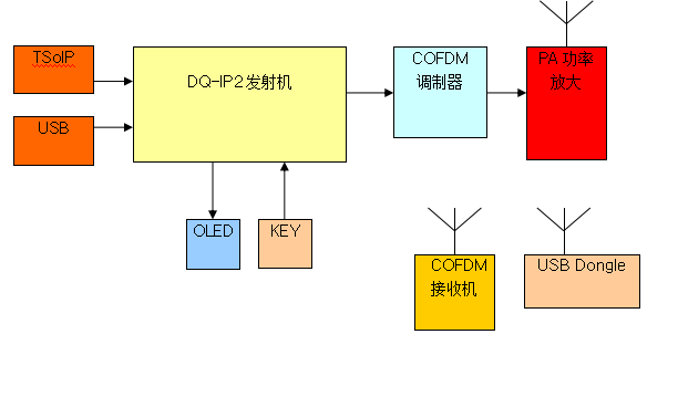
5.1 System composition
The schematic diagram of the DQ-IP2 transmitter is as follows:
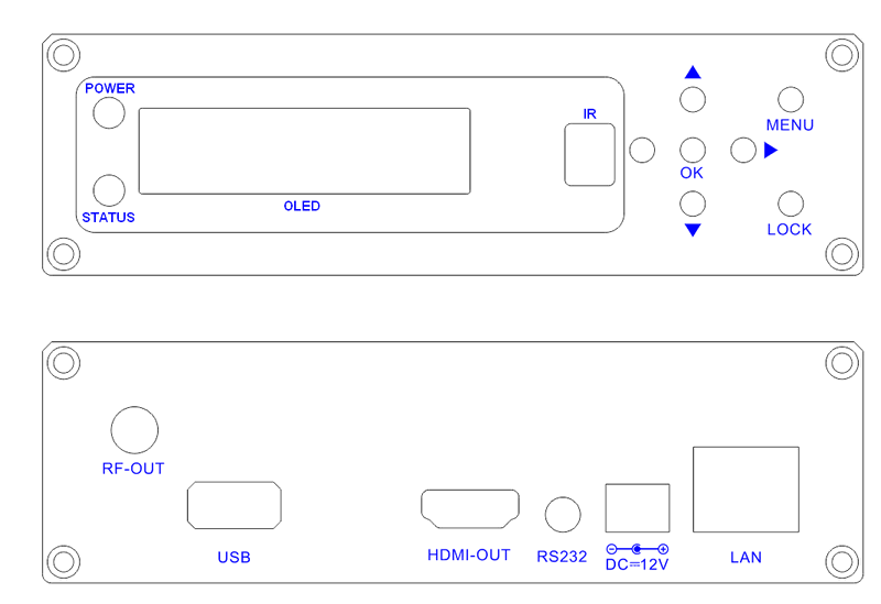
Structure diagram (front panel diagram)
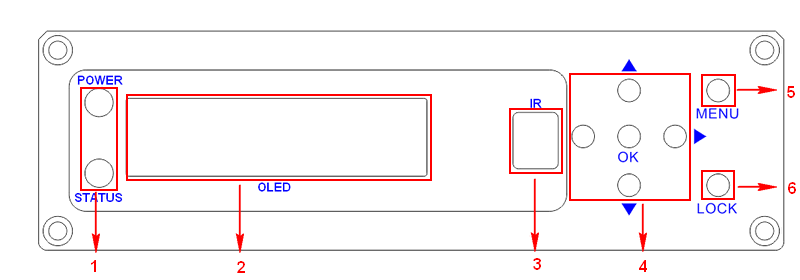
|
1 |
Power indicator, Status indicator |
|
2 |
OLED display interface |
|
3 |
IR remote control receiver |
|
4 |
Up, down, left, right, confirm button |
|
5 |
Menu button |
|
6 |
Lock button |
Schematic diagram of structure (schematic diagram of rear panel)
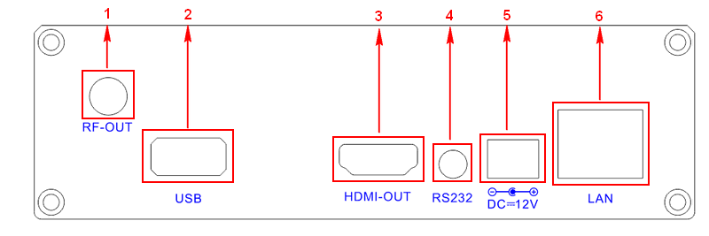
|
1 |
RF output interface |
|
2 |
USB interface |
|
3 |
HDMI output interface |
|
4 |
RS232 serial port |
|
5 |
DC12V power interface |
|
6 |
Ethernet interface |
6 Front panel operation guide
6.1 Keyboard function
◀Left, ▶Right keys: move the cursor and modify parameters;
▲Up and ▼Down keys: Menu page turning and parameter modification;
Confirm key (OK): Enter the submenu and confirm the new parameter changes and execute the function selection;
Menu key (MENU): enter the main menu or return to the previous menu;
Lock key (LOCK): lock/unlock panel keys;
Note:
A. When the keyboard is locked, press any key to activate the panel, and press the lock key.
Unlock the keyboard and enter the main menu;
B. After 60 seconds of not operating the keyboard, the keyboard will be automatically locked;
6.2 Menu selection
6.2.1 Main interface and first-level submenu
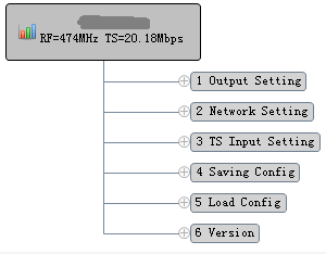
The main interface is shown in the figure below. The main interface displays system information. RF is the modulation frequency and TS is the input bit rate.

Press the MENU button to enter the first-level submenu:
1 Output Setting COFDM modulation parameter setting and RF output switch control;
2 Network Setting 2 Network Setting network parameter setting;
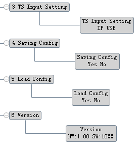
3 TS Input Setting3 TS Input Setting select the source of the input TS stream, from the network or USB;
4 Saving Config saves the setting parameters to Flash;
5 Load Config Load setting parameters from Flash;
6 Version displays the hardware version and software version information;
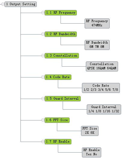
6.2.2 Output settings
RF Enable" set whether to turn on the modulator output
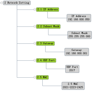
6.2.3 Network settings
"MAC" displays the MAC address of the machine
6.2.4 Other settings
6.3 Panel operation process
Press the MENU key to enter the first-level sub-menu, then press the ▲▼ key to switch the menu, press the OK key to confirm the menu, and enter the sub-menu.
Then press ◀▶ to switch the setting items, press ▲▼ to set the parameters, after setting the parameters, press the OK button to confirm the modification, after the modification is completed, if you want to save the setting parameters to the Flash, enter the "Saving Config" menu, save The parameters are stored in Flash, and the saved setting parameters will be automatically loaded after the next power-on. If you do not save the parameters, the new setting parameters will not be loaded after the next power-on.
6.4 System boot process
After the system is powered on, the OLED panel displays BOOT, then displays ON, loads the configuration parameters from Flash, then displays the main interface, and scrolls the display information.
6.5 System operation errors and troubleshooting
6.5.1 Indicator status
There are 2 LED indicators on the panel, which are described as follows:
1 "POWER" is the power indicator. When the power switch is turned on, the indicator light is on (red), indicating that the power supply of the device is working normal.
2 “STATUS”指示灯亮(绿色),表示设备工作正常。2 The "STATUS" indicator is on (green), indicating that the device is working normally.
6.5.2 Common troubleshooting
6.5.2.1 "POWER" power indicator does not light up
Please check whether the power adapter has a 12V voltage output and whether it is plugged into the DC socket.
6.5.2.2 "STATUS" status indicator does not light up
The device is not working properly, check whether the network parameter configuration is correct.

Dingxin Technology (Shenzhen) Co., LTD
Contact: Mr. Feng Tel: +86-18820485306
E-mail: robin@dechoin.com QQ:1541281865
Address: Jin Cheng Road, Shajing Street, Bao'an District, Shenzhen City, Guangdong Province
Copyright © Dingxin Technology (Shenzhen) Co., LTD 【Backstage management】

